
목적
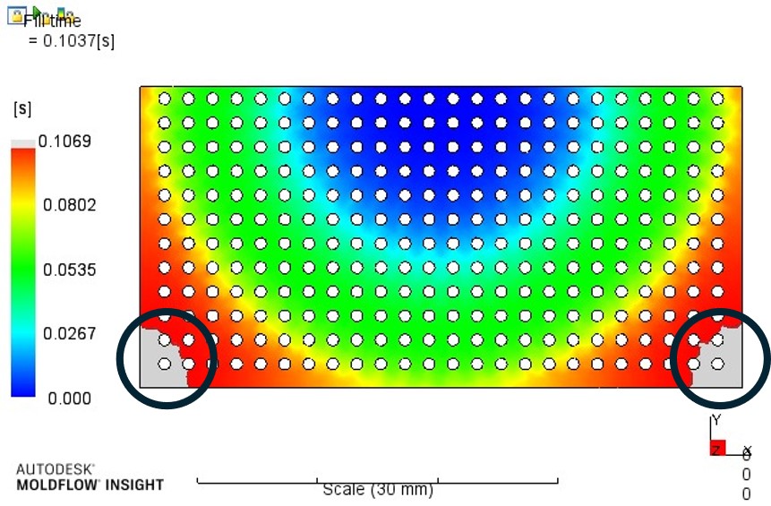
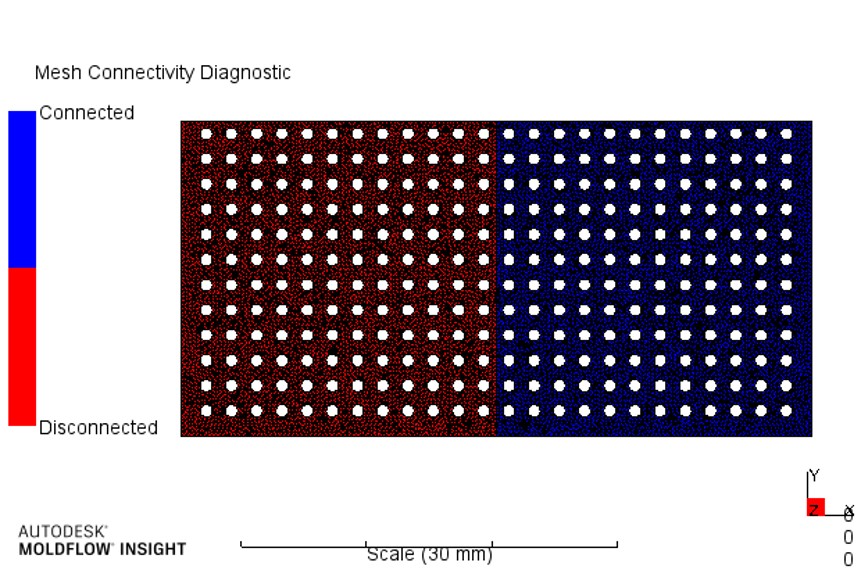
대칭 제품 해석시 좌우 Mesh의 형태가 균일하지 못할 경우, 충진 패턴이 대칭으로 나타나지 않을 수 있습니다. 대칭 제품의 경우 [Reflect] 기능을 사용하여 대칭된 Mesh 형태를 만들 수 있습니다. 하지만, 이럴 경우 Original Mesh와 Reflect Mesh 가 연결되지 않습니다. 연결되지 않은 Mesh 들을 연결해주기 위해서 [Global Merge] 기능을 이용하여 간단하게 Mesh를 연결 가능합니다.
방법
이러한 문제를 해석 전에 확인하는 방법은 간단합니다. [Mesh Edit]에서 [Global Merge]를 실행하여 해결할 수 있습니다.
따라하기
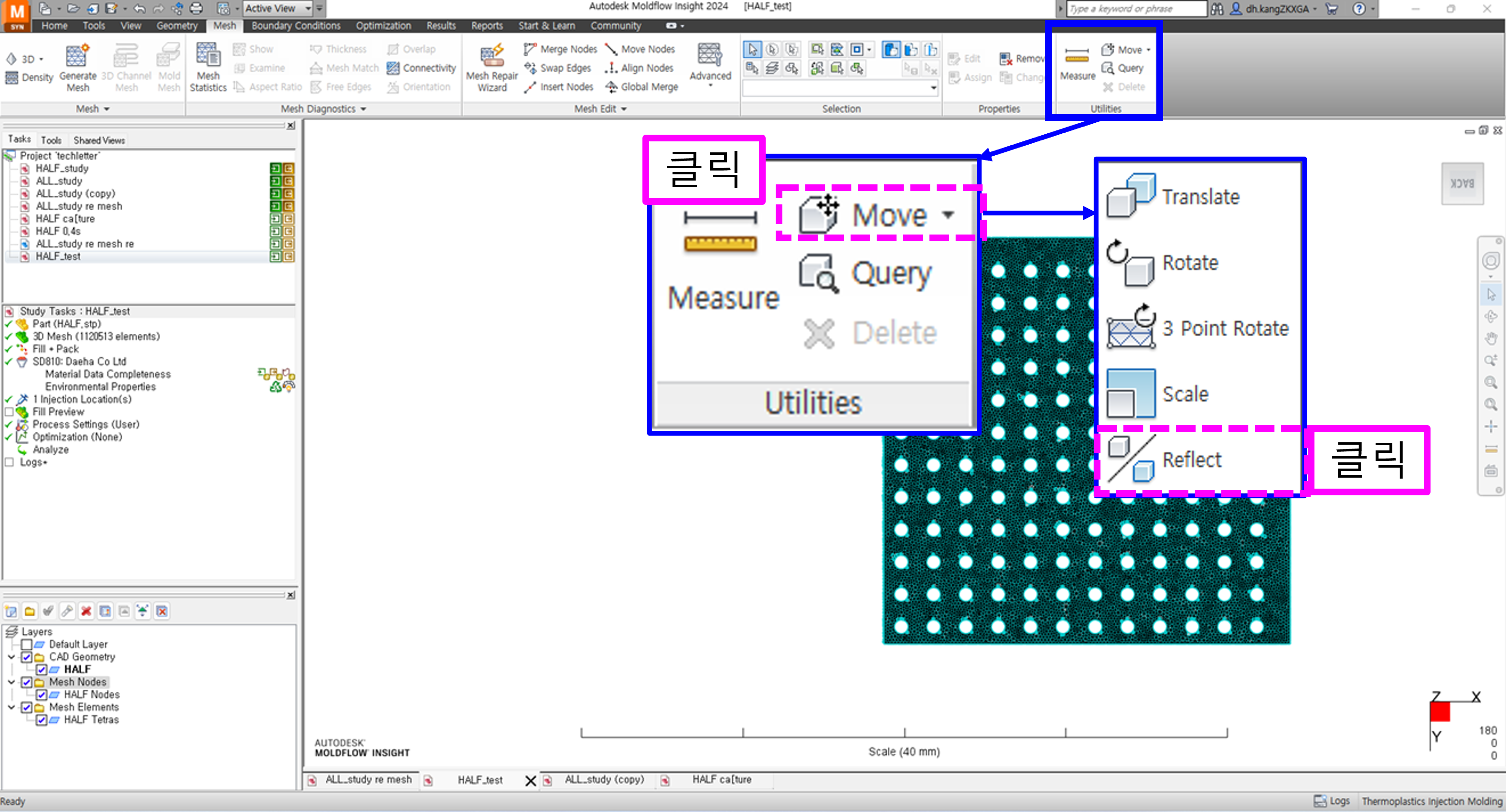
1. Mesh탭이나 Geometry탭의 [Utilities]에서 [Move]클릭 후 [Reflect]
기능을 선택
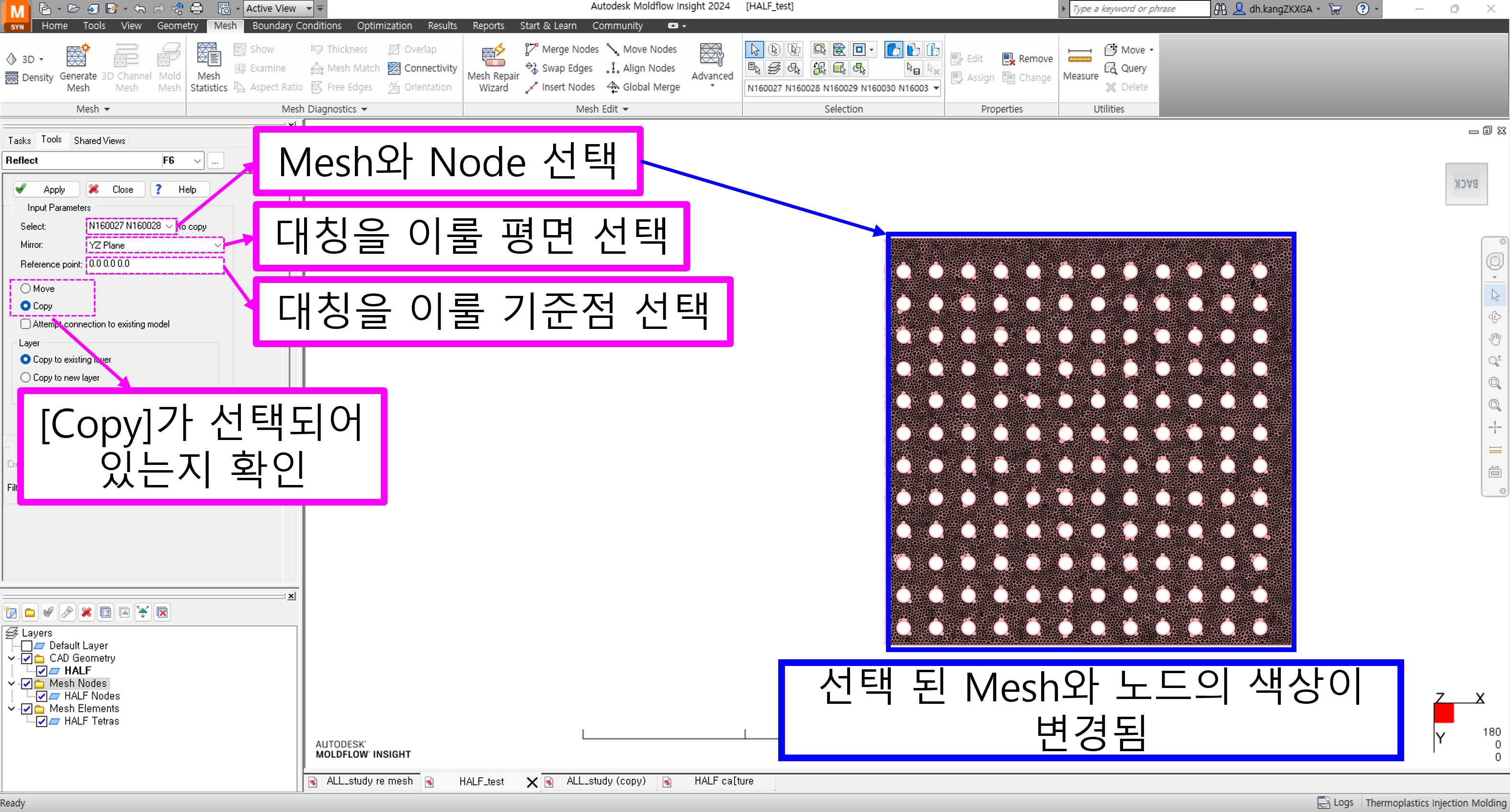
2. 대칭할 Mesh와 Node를 선택한 후, 대칭의 기준이 될 평면과 기준점을
선택
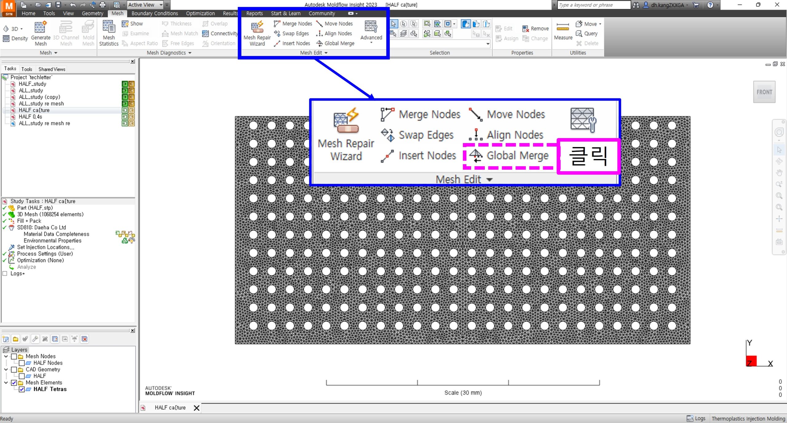
3. Mesh 탭의 [Mesh Edit]에서 [Global Merge] 클릭
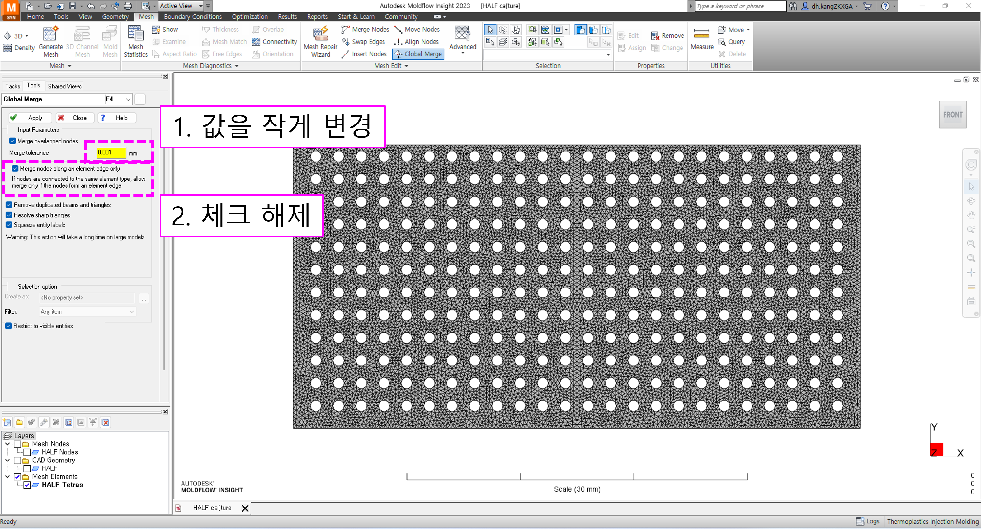
4. [Merge tolerance]의 값을 매우 작게 설정 후, [Merge nodes along an element edge only] 옵션 해제
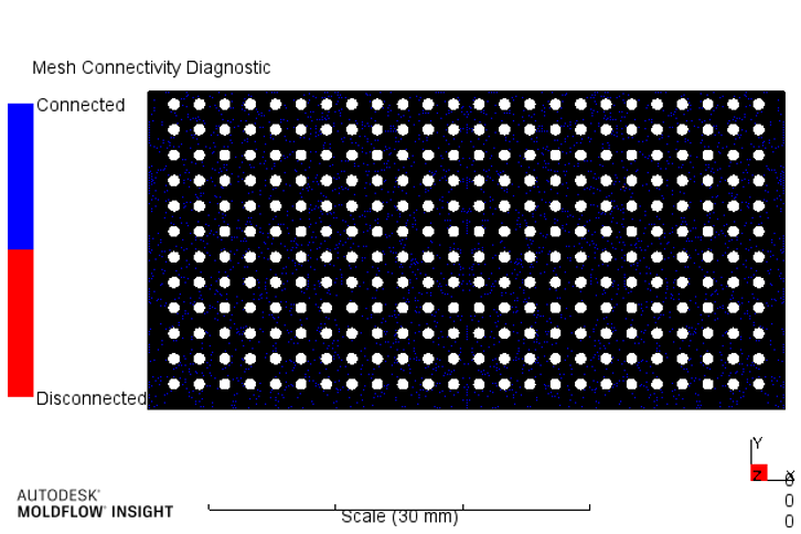
5. Mesh 탭에서 [Connectivity]를 통해 전체가 연결되는 것을 확인 가능
6. 충진 패턴이 동일하게 나타나는 것을 확인 가능
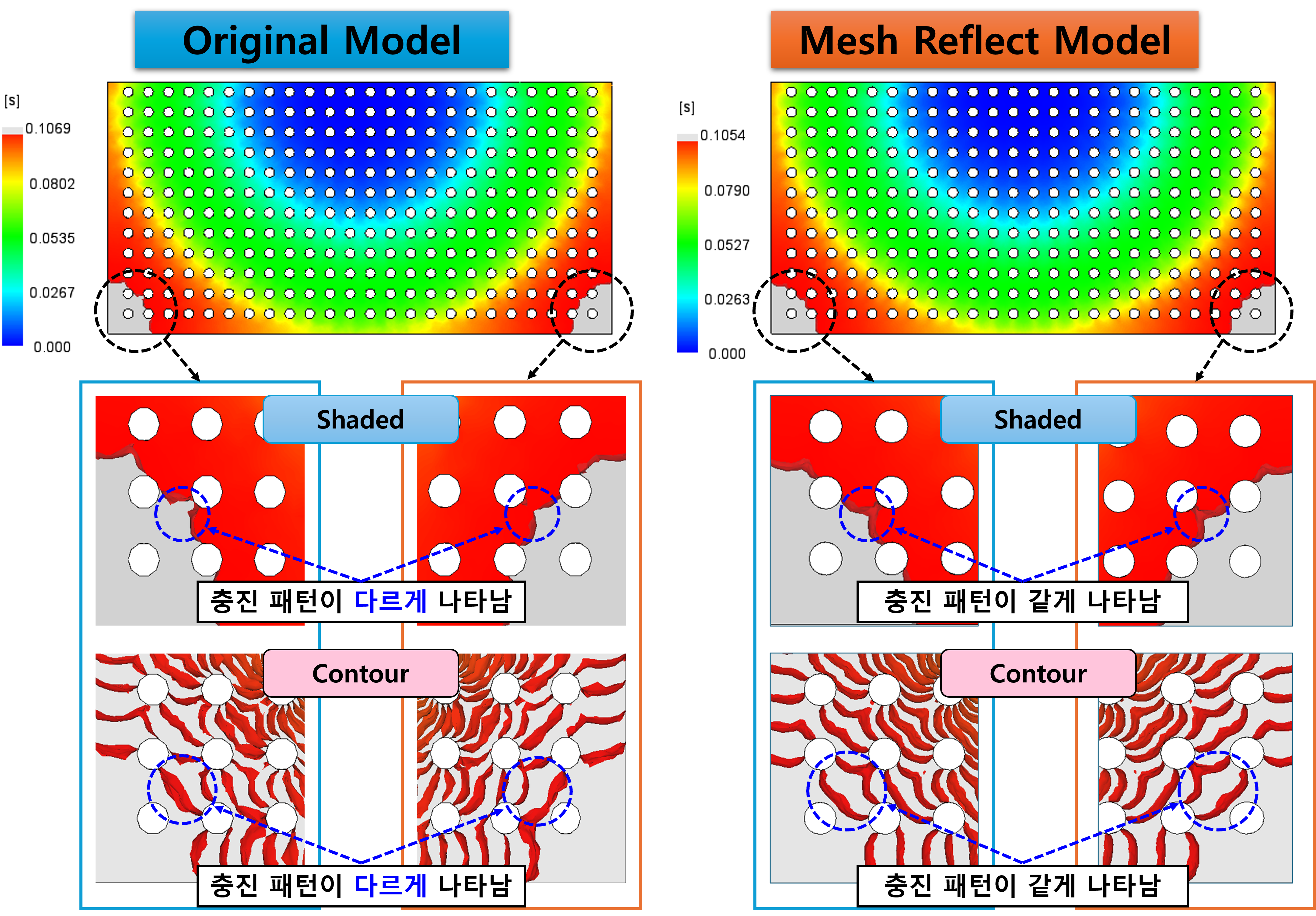
향후 좌우 대칭의 제품 모델에 대한 해석을 진행하시는 경우, Reflect 기능을 사용하시어 Mesh 형태에 의한 비대칭 충진 효과를 최소한으로 줄이시길 바랍니다.