
목적
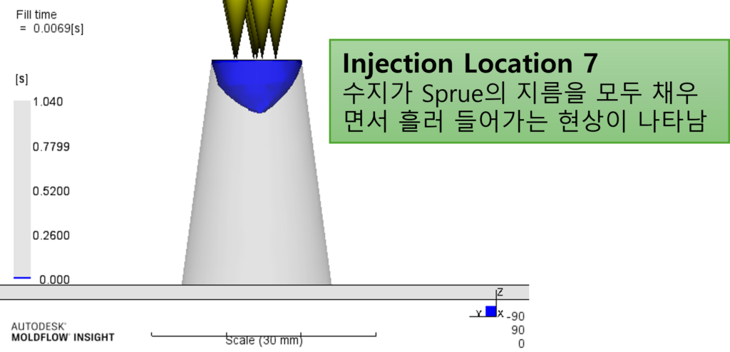
Sprue를 Beam요소로 사용할 수 있지만, 모델링하여 3D Mesh로 생성 후 속성을 부여하여 나타낼 수 있습니다. 이때, Injection Location을 한 개의 노드에만 생성하는 것이 아닌 엣지를 제외한 모든 면적에 생성해야합니다.
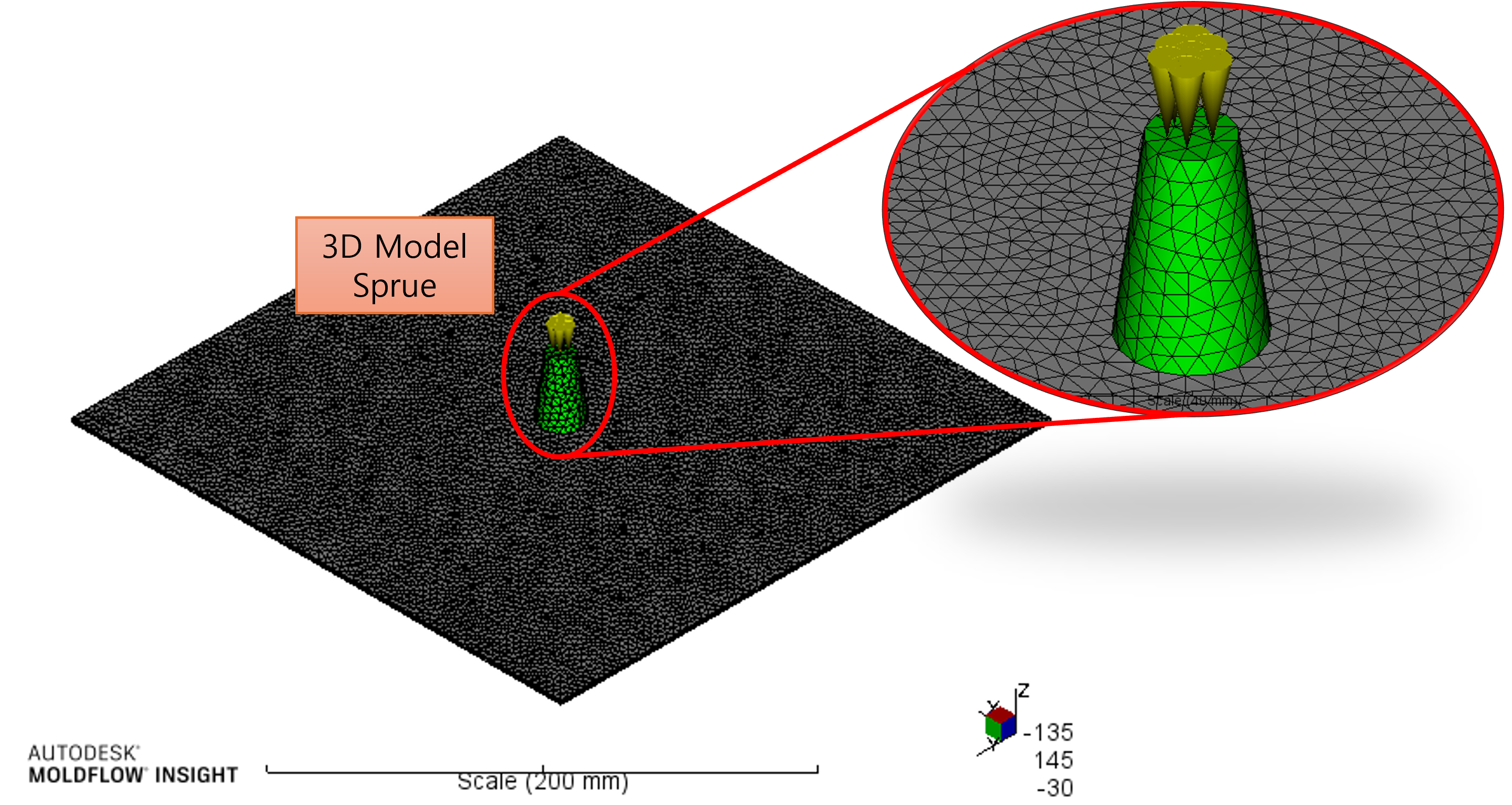
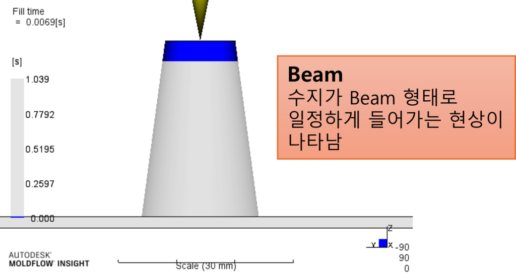
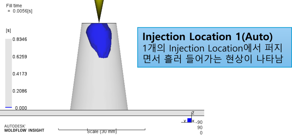
초기에 수지가 주입되는 모양이 달라지기 때문입니다. 이러한 현상은 충진 패턴에 영향을 줄 수 있습니다.
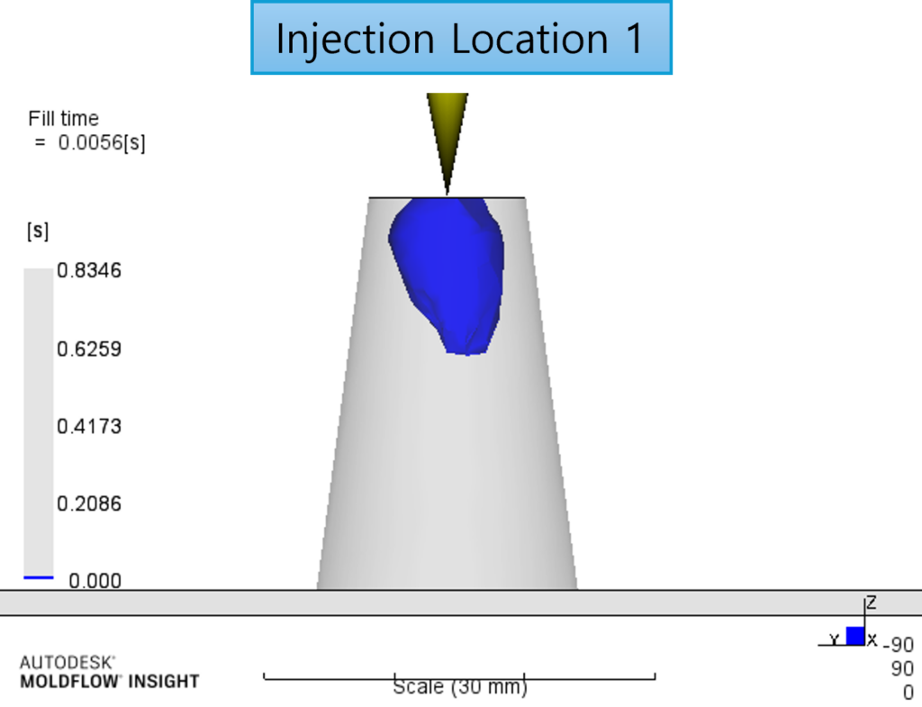
3D 모델링의 스프루를 사용할 때 Injection Location을 1개만 생성했을 경우 선택할 수 있는 옵션이 있습니다.
따라하기
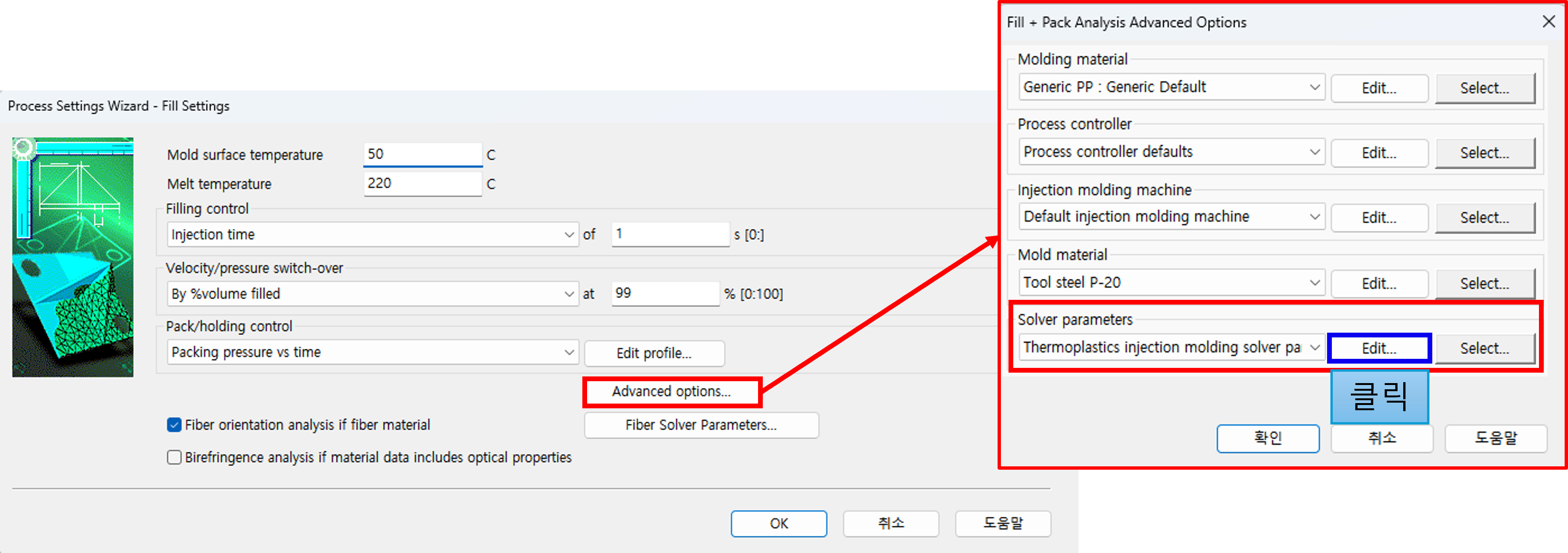
1. [Process Setting]클릭 > [Advanced options…]선택>
[Solver parameters]의 [Edit]를 클릭합니다.
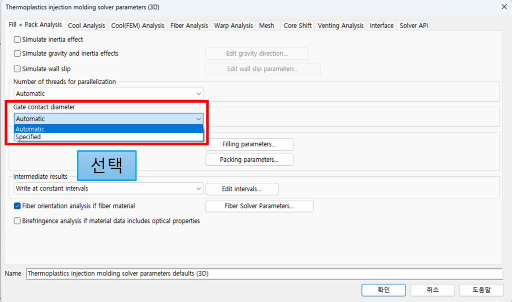
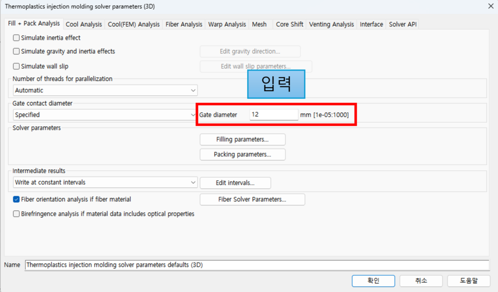
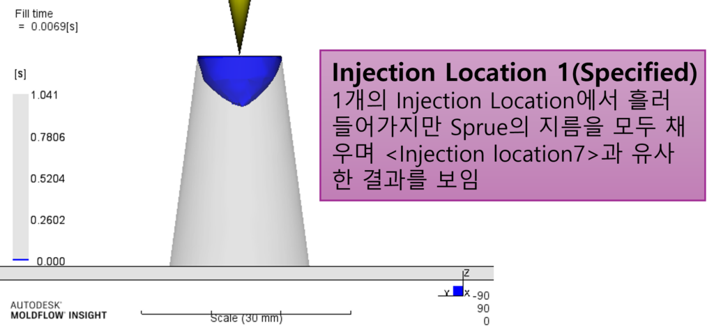
2. [Gate contact diameter]항목에서 [Specified]선택> Gate Diameter 입력합니다. (Default는 Automatic)
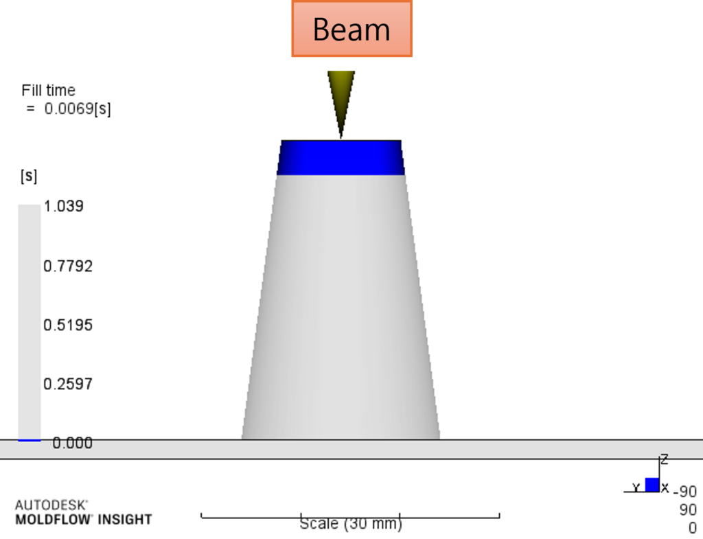
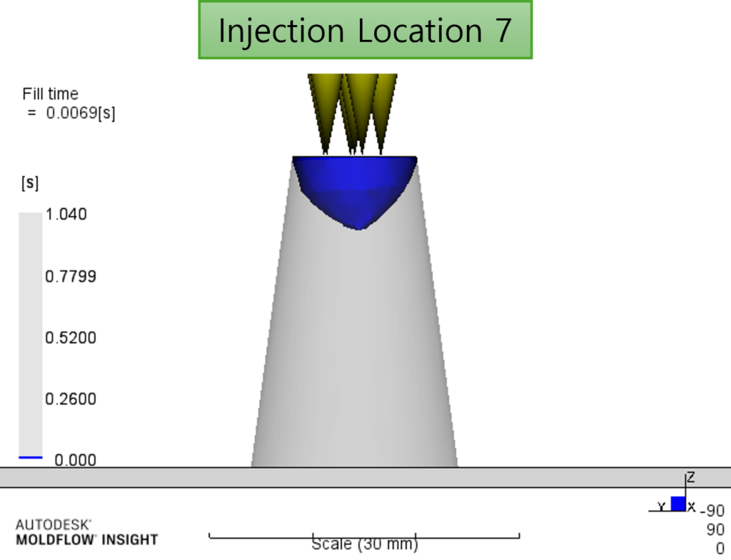
3. 해석을 진행하여 결과를 비교해보면 다음과 같습니다.
지금까지 3D Mesh로 만든 스프루에서 왜 여러 Injection Location을 생성해야 하는지 알아봤습니다.