PADS Pro의 부품들은 부품이 배치될 공간을 2D형상으로 작성하여 3D의 모델을 Assign가능합니다.
하지만 3D의 모델이 없는 경우에는 2D형상의 특정 부품영역의 Layer의 형상을 작성하고, 높이 값을 입력하여 3D형상을 구현할 수 있습니다.
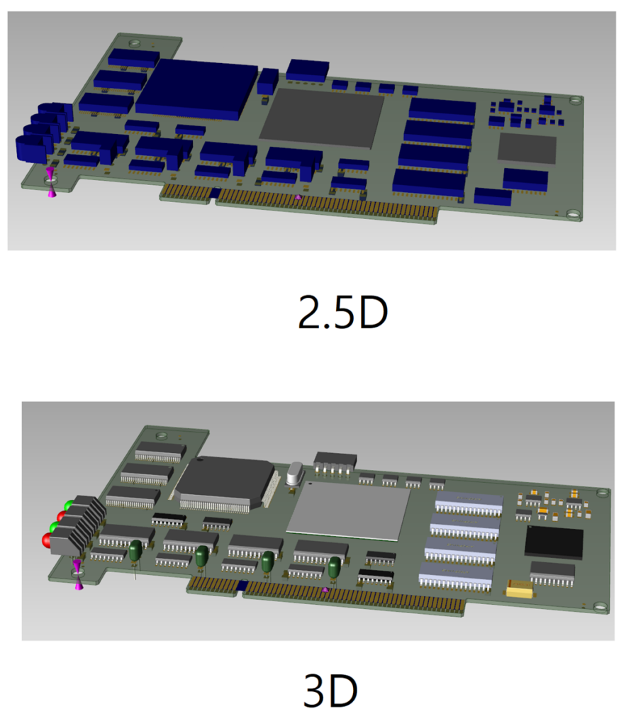
정밀한 형상의 부품이 굳이 필요하지 않으면 높이 값을 입력하는 것만으로도 충분한 2.5D의 PCB 부품 형상을 구현 가능합니다.
1. 부품의 높이 값을 부여해서 2.5D까지 만들면 왠만한 Mechanical Assembly와 간섭 Check가 가능합니다.
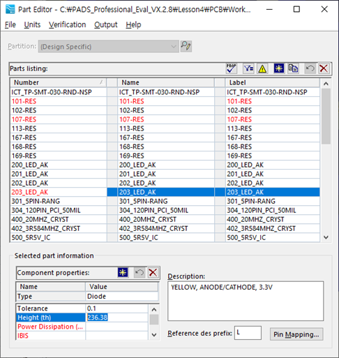
2. 부품의 높이 값은 부품의 Properties에서 Part와 Cell의 값 모두 확인 가능하며 우선순위는 Part의 값입니다.
(주의 사항: Part의 값이 0이면 0으로 인식합니다. Cell의 값으로 인식하려면 Part의 값이 없어야 합니다.)
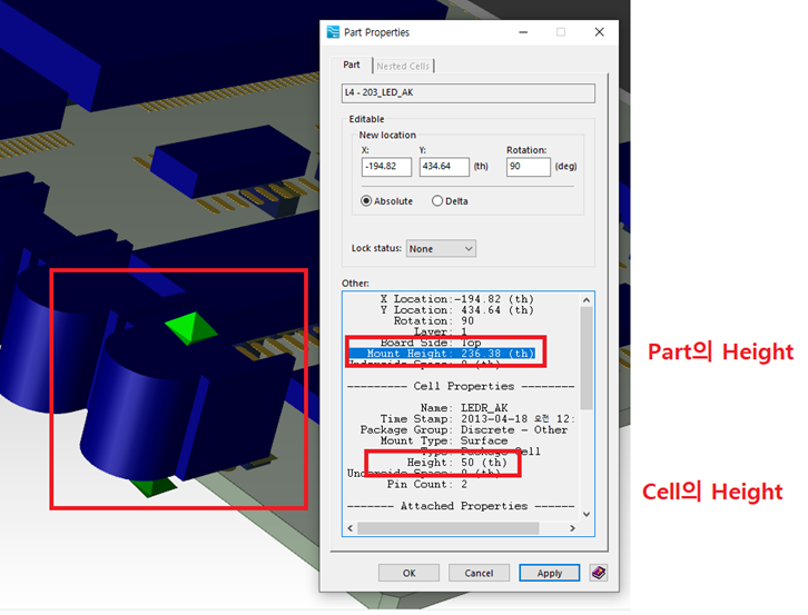
3. Part의 Height는 Part Editor의 component Properties에서 설정 가능합니다.
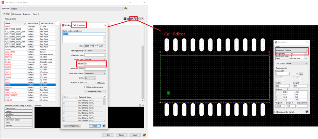
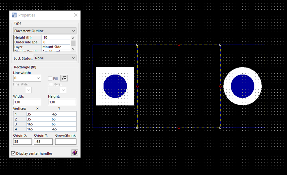
4. Cel의 Height는 Cell Editor의 Properties에서 확인 가능하며, 이 값은 Cell Editor의 Placement outline의 속성의 Height값이며, 변경하면 양쪽이 동일하게 변경됩니다.
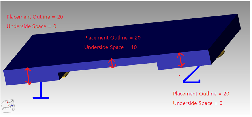
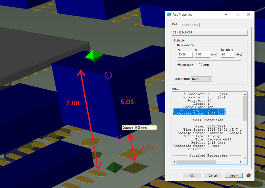
5. 부품의 실장까지 고려해서 Height와 같이 사용되는 값이 Underside Space값입니다. Underside Space값은 부품을 Board로부터 띠우는 값으로 아래처럼 Part와 Cell에 설정 가능합니다.
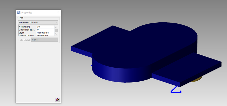
6. Cell에서 Height가 인식되는 Type은 Placement Outline입니다.
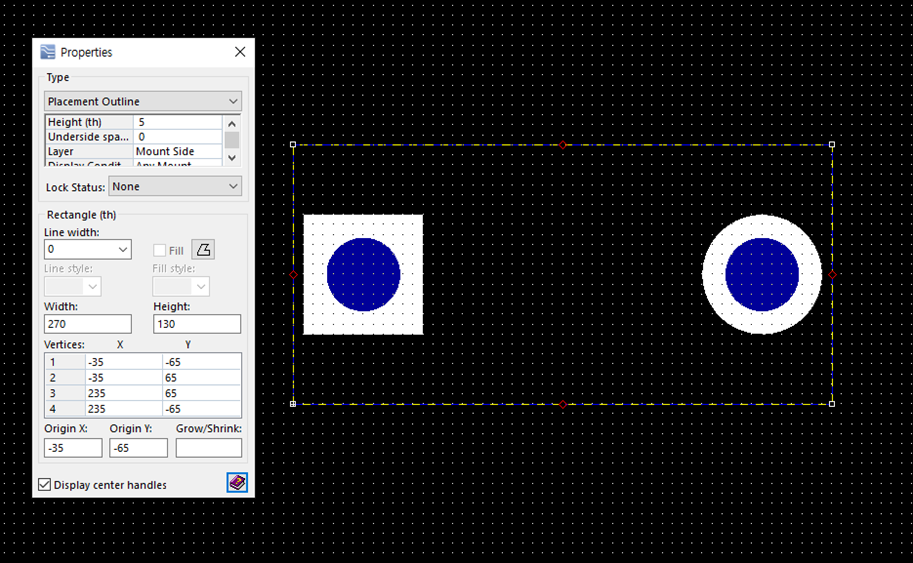
7. 이 Placement Outline은 1개만 사용하는 것이 아니라 여러 개로 만들 수 있습니다.
8. PADS Pro에서는 Placement Outline과 Underside Space를 조합하면 더욱더 정밀한 2.5D를 만들 수가 있습니다.